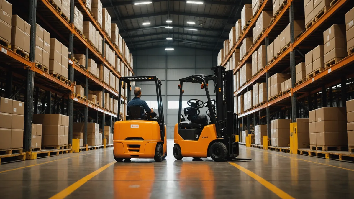
A forklift reversing at low speed is one of the hardest obstacle scenarios for an AMR perception pipeline to handle correctly. It is not because forklifts are difficult to detect — their LiDAR signature is distinctive and large. It is because of the specific combination of behaviors: low speed, unpredictable reversing direction, significant size relative to aisle width, and the fact that the AMR may be approaching from behind where the forklift operator has limited visibility.
We spent a lot of time on this problem specifically because it is the most safety-critical scenario in mixed human-robot operations. Here is the full detection pipeline from raw LiDAR frame to confirmed classification with trajectory, including where we made tradeoffs and why.
Why Forklifts Are Hard to Classify, Not Just Detect
The first version of our obstacle classifier treated forklift detection as a size problem: things above a certain bounding box size that were also moving got flagged as large mobile obstacles. This worked well enough for forklifts moving forward at moderate speed. It failed in two specific scenarios: forklifts moving slowly (under 0.5 m/s, which is common during maneuvering in tight aisles) and forklifts during the moment of direction reversal — the transition from forward to reverse or reverse to forward.
A forklift slowing to near-zero before reversing looks, to a naive velocity-based classifier, like a large static obstacle for 1 to 3 seconds. During those seconds, the robot's planner may initiate a path around what it believes is a parked machine, only to have the "static" obstacle begin moving rapidly into the robot's planned path.
The classification problem is not "is there a big thing there" — that is trivially solved with a size threshold. The problem is "is this big thing about to start moving, and in which direction." That requires a different input than just the current frame.
Stage 1: Point Cluster Extraction (T=0 to T=8ms)
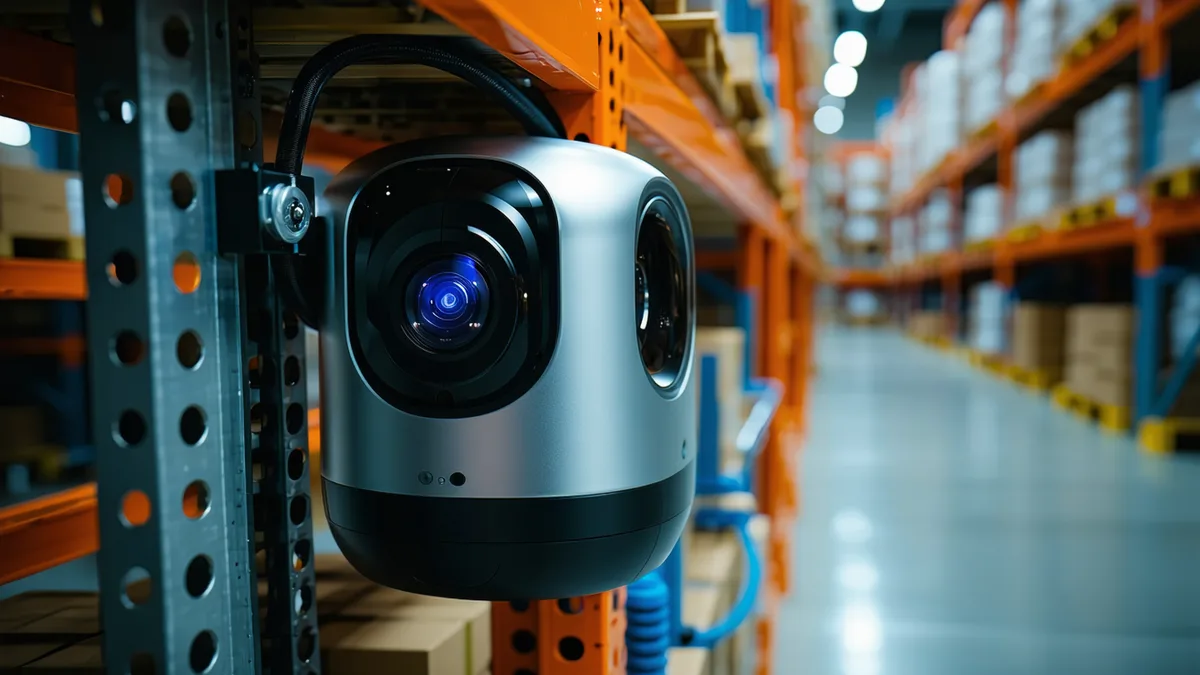
Raw LiDAR scan arrives as a /scan LaserScan message at 10 Hz (100 ms per scan). Our pipeline begins processing immediately on message receipt. The first stage is point cluster extraction using a modified DBSCAN algorithm optimized for the expected point density of 2D LiDAR scans (typically 360 to 1080 points per scan depending on angular resolution).
DBSCAN parameters for our warehouse configuration:
epsilon: 0.15   # 15cm neighborhood radius
min_samples: 3  # minimum points to form a cluster
min_cluster_size: 4   # discard clusters smaller than 4 points
max_cluster_size: 200 # discard likely-noise oversized clusters
For a typical warehouse scene with 4 to 8 distinct obstacles visible in the scan, cluster extraction completes in 2 to 5 ms on our target hardware (Intel NUC 12th gen Core i5). Each cluster is represented as a centroid position, bounding box estimate, and point count. This is the fast path — we need this output to begin tracking before the classification stage completes.
Stage 2: Multi-Object Tracker Update (T=8ms to T=22ms)
Each extracted cluster is matched against the existing obstacle tracker state using a nearest-centroid matching algorithm. The tracker maintains a list of active obstacle tracks, each with:
- Centroid position history (last 15 scan frames, 1.5 second window)
- Bounding box size history (to detect size changes from partial vs full visibility)
- Velocity estimate from a Kalman filter over centroid displacement
- Classification label with confidence score
- Frames since last confirmed observation (decay counter)
The Kalman filter velocity estimate is the key input for the reversing forklift problem. A forklift's velocity history over the 1.5-second window shows the deceleration and reversal signature: a track that was moving at +0.8 m/s (forward), slows to near-zero over 3 to 5 frames, then begins showing negative displacement velocity. The rate of velocity change during the deceleration phase — the estimated deceleration — becomes an important input to Stage 3.
Track matching and Kalman update complete in 8 to 12 ms.
Stage 3: Classification with Kinematic Context (T=22ms to T=55ms)
Classification uses a combination of geometric features from the current cluster (bounding box dimensions, aspect ratio, point density) and kinematic features from the tracker (velocity magnitude, velocity direction, deceleration estimate, track age). The feature vector fed to the classifier:
feature vector (per obstacle track):
  bbox_width_m          # bounding box width in meters
  bbox_length_m         # bounding box length in meters
  bbox_area_m2          # bounding box area
  point_density         # points per square meter within bbox
  velocity_magnitude    # |v| in m/s from Kalman estimate
  velocity_direction    # heading angle in radians, robot-relative
  decel_estimate        # estimated deceleration m/s^2 over last 0.5s
  track_age_frames      # how many frames this track has been observed
  size_variance         # variance in bbox size over last 10 frames
  is_near_reversal      # bool: |v| < 0.3 m/s AND decel_estimate > 0.4
The is_near_reversal feature is the flag that triggers the forklift-specific classification path. A track with near-zero velocity AND significant deceleration in the recent history is a candidate for the "large machine about to reverse" class, which gets handled with a different safety margin than a genuinely static large obstacle.
The classifier itself is a gradient-boosted tree (XGBoost, depth 6, 150 estimators) trained on labeled warehouse LiDAR log data. For a forklift at typical detection ranges (2 to 8 m), classification accuracy on our test set is 94.3% for forward-moving, 91.7% for stationary, and 88.1% for the near-reversal state. The near-reversal accuracy is lower because the feature signatures overlap with other slow-moving large objects (manual pallet jacks, large carts), but the safety consequence of a false positive here is just a conservative wait, not a collision — so the asymmetry in consequences makes this acceptable.
Stage 4: Trajectory Prediction and Safety Margin Calculation (T=55ms to T=72ms)
For a classified forklift with a confirmed trajectory estimate, we generate a 1.5-second predicted position envelope. For forward-moving forklifts, this is a linear projection of current velocity with a ±15° heading uncertainty cone. For near-reversal state forklifts, we generate a bimodal prediction: either the forklift continues slowing and stops, or it reverses at estimated reversal speed (default 0.6 m/s based on typical maneuvering speed), in the direction opposite to its last confirmed heading.
The predicted position envelope at T+1500ms is inflated by the forklift's bounding box size plus a safety margin determined by confidence score: high-confidence classifications get a 0.4 m margin, medium-confidence get 0.7 m, and near-reversal uncertain states get 1.0 m. This inflated envelope is what gets inserted into the obstacle costmap as a predicted obstacle zone — not just where the forklift is now, but where it might be when the robot finishes its current planning cycle and begins executing the plan.
End-to-End Latency
From raw LiDAR scan arrival to classification result available in the costmap layer:
- Stage 1 (cluster extraction): 2–5 ms
- Stage 2 (tracker update): 8–12 ms
- Stage 3 (classification): 18–28 ms
- Stage 4 (trajectory + costmap update): 12–18 ms
- Total: 40–63 ms typical, 80 ms 99th percentile
The 99th percentile figure includes scheduling jitter from the ROS 2 executor and occasional classifier inference spikes when the tracker has a large number of active tracks (typically during peak shift periods when obstacle density is highest). The 80 ms bound we cite publicly is the 99th percentile, not the median — we are not quoting the best case.
At a robot travel speed of 1.0 m/s, 80 ms of detection latency means the robot has traveled 80 mm from when the scan was taken to when the costmap reflects the obstacle. Combined with the robot's braking distance (approximately 200 to 400 mm at 1.0 m/s depending on surface and robot mass), the effective safety stop distance from confirmed detection to full stop is approximately 280 to 480 mm. This is why the forklift safety margin of 400 to 1000 mm inflated into the costmap ahead of detected forklift positions is calibrated the way it is — it is the distance the robot needs to be away from the forklift before the stop-or-reroute decision is made, not the distance from the forklift itself.